ASME FLANGE DIMENSIONS IN MILLIMETERS
CLASS 150
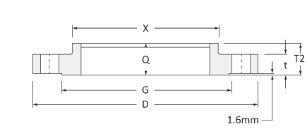
Threaded flange dimensions class 150 in millimeters (ASME B16.5)
Size
inch |
D
mm |
X
mm |
G
mm |
t
mm |
T2
mm |
Q
mm |
| 1/2 |
89 |
30.2 |
35.1 |
11.2 |
15.7 |
15.7 |
| 3/4 |
99 |
38.1 |
42.9 |
12.7 |
15.7 |
15.7 |
| 1 |
108 |
49.3 |
50.8 |
14.2 |
17.5 |
17.5 |
| 1¼ |
117 |
58.7 |
63.5 |
15.7 |
20.6 |
20.6 |
| 1½ |
127 |
65.0 |
73.2 |
17.5 |
22.4 |
22.4 |
| 2 |
152 |
77.7 |
91.9 |
19.1 |
25.4 |
25.4 |
| 2½ |
178 |
90.4 |
104.6 |
22.4 |
28.4 |
28.4 |
| 3 |
191 |
108.0 |
127.0 |
23.9 |
30.2 |
30.2 |
| 3½ |
216 |
122.2 |
139.7 |
23.9 |
31.8 |
31.8 |
| 4 |
229 |
134.9 |
157.2 |
23.9 |
33.3 |
33.3 |
| 5 |
254 |
163.6 |
185.7 |
23.9 |
36.6 |
36.6 |
| 6 |
279 |
192.0 |
215.9 |
25.4 |
39.6 |
39.6 |
| 8 |
343 |
246.1 |
269.7 |
28.4 |
44.5 |
44.5 |
| 10 |
406 |
304.8 |
323.9 |
30.2 |
49.3 |
49.3 |
| 12 |
483 |
365.3 |
381.0 |
31.8 |
55.6 |
55.6 |
| 14 |
533 |
400.1 |
412.8 |
35.1 |
57.2 |
57.2 |
| 16 |
597 |
457.2 |
469.9 |
36.6 |
63.5 |
63.5 |
| 18 |
635 |
505.0 |
533.4 |
39.6 |
68.3 |
68.3 |
| 20 |
699 |
558.8 |
584.2 |
42.9 |
73.2 |
73.2 |
| 24 |
813 |
663.4 |
692.2 |
47.8 |
82.6 |
82.6 |
| Size |
Bolts Drilling |
Bolting Requirements |
| inch |
Bolt circle
Diameter mm |
Holes # |
Holes Dia. mm |
Bolt Dia. inch. |
Length
FF Flange |
Length
RF Flange |
Length
RTJ Flange |
| 1/2 |
60.5 |
4 |
15.7 |
1/2 |
50.8 |
57.2 |
– |
| 3/4 |
69.9 |
4 |
15.7 |
1/2 |
50.8 |
63.5 |
– |
| 1 |
79.2 |
4 |
15.7 |
1/2 |
57.2 |
63.5 |
76.2 |
| 1¼ |
88.9 |
4 |
15.7 |
1/2 |
57.2 |
69.9 |
82.6 |
| 1½ |
98.6 |
4 |
15.7 |
1/2 |
63.5 |
69.9 |
82.6 |
| 2 |
120.7 |
4 |
19.1 |
5/8 |
69.9 |
82.6 |
95.3 |
| 2½ |
139.7 |
4 |
19.1 |
5/8 |
76.2 |
88.9 |
101.6 |
| 3 |
152.4 |
4 |
19.1 |
5/8 |
76.2 |
88.9 |
101.6 |
| 3½ |
177.8 |
8 |
19.1 |
5/8 |
76.2 |
88.9 |
101.6 |
| 4 |
190.5 |
8 |
19.1 |
5/8 |
76.2 |
88.9 |
101.6 |
| 5 |
215.9 |
8 |
22.4 |
3/4 |
82.6 |
95.3 |
108.0 |
| 6 |
241.3 |
8 |
22.4 |
3/4 |
82.6 |
101.6 |
114.3 |
| 8 |
298.5 |
8 |
22.4 |
3/4 |
88.9 |
108.0 |
120.7 |
| 10 |
362.0 |
12 |
25.4 |
7/8 |
101.6 |
114.3 |
127.0 |
| 12 |
431.8 |
12 |
25.4 |
7/8 |
101.6 |
120.7 |
133.4 |
| 14 |
476.3 |
12 |
28.4 |
1 |
114.3 |
133.4 |
146.1 |
| 16 |
539.8 |
16 |
28.4 |
1 |
114.3 |
133.4 |
146.1 |
| 18 |
577.9 |
16 |
31.8 |
11/8 |
127.0 |
146.1 |
158.8 |
| 20 |
635.0 |
20 |
31.8 |
11/8 |
139.7 |
158.8 |
171.5 |
| 24 |
749.3 |
20 |
35.1 |
1¼ |
152.4 |
171.5 |
184.2 |
CLASS 300
Threaded flange dimensions class 300 in millimeters (ASME B16.5)
Size
inch |
D
mm |
X
mm |
G
mm |
t
mm |
B
mm |
T2
mm |
Q
mm |
| 1/2 |
95 |
38.1 |
35.1 |
14.2 |
23.6 |
22.4 |
15.7 |
| 3/4 |
117 |
47.8 |
42.9 |
15.7 |
29.0 |
25.4 |
15.7 |
| 1 |
124 |
53.8 |
50.8 |
17.5 |
35.8 |
26.9 |
17.5 |
| 1¼ |
133 |
63.5 |
63.5 |
19.1 |
44.5 |
26.9 |
20.6 |
| 1½ |
155 |
69.9 |
73.2 |
20.6 |
50.5 |
30.2 |
22.4 |
| 2 |
165 |
84.1 |
91.9 |
22.4 |
63.5 |
33.3 |
28.4 |
| 2½ |
191 |
100.1 |
104.6 |
25.4 |
76.2 |
38.1 |
31.8 |
| 3 |
210 |
117.3 |
127.0 |
28.4 |
92.2 |
42.9 |
31.8 |
| 3½ |
229 |
133.4 |
139.7 |
30.2 |
104.9 |
44.5 |
36.6 |
| 4 |
254 |
146.1 |
157.2 |
31.8 |
117.6 |
47.8 |
36.6 |
| 5 |
279 |
177.8 |
185.7 |
35.1 |
144.5 |
50.8 |
42.9 |
| 6 |
318 |
206.2 |
215.9 |
36.6 |
171.5 |
52.3 |
46.0 |
| 8 |
381 |
260.4 |
269.7 |
41.1 |
222.3 |
62.0 |
50.8 |
| 10 |
445 |
320.5 |
323.9 |
47.8 |
276.4 |
66.5 |
55.6 |
| 12 |
521 |
374.7 |
381.0 |
50.8 |
328.7 |
73.2 |
60.5 |
| 14 |
584 |
425.5 |
412.8 |
63.8 |
360.4 |
76.2 |
63.5 |
| 16 |
648 |
482.6 |
469.9 |
57.2 |
411.2 |
82.6 |
68.3 |
| 18 |
711 |
533.4 |
533.4 |
60.5 |
462.0 |
88.9 |
69.9 |
| 20 |
775 |
587.2 |
584.2 |
63.5 |
512.8 |
95.3 |
73.2 |
| 24 |
914 |
701.5 |
692.2 |
69.9 |
614.4 |
106.4 |
82.6 |
| Size |
Bolts Drilling |
Bolting Requirements |
| inch |
Bolt circle
Diameter mm |
Holes # |
Holes Dia. mm |
Bolt Dia. inch. |
Length
FF Flange |
Length
RF Flange |
Length
RTJ Flange |
| 1/2 |
66.5 |
4 |
15.7 |
1/2 |
57.2 |
63.5 |
76.2 |
| 3/4 |
82.6 |
4 |
19.1 |
5/8 |
63.5 |
76.2 |
88.9 |
| 1 |
88.9 |
4 |
19.1 |
5/8 |
63.5 |
76.2 |
88.9 |
| 1¼ |
98.6 |
4 |
19.1 |
5/8 |
69.9 |
82.6 |
95.3 |
| 1½ |
114.3 |
4 |
22.4 |
3/4 |
76.2 |
88.9 |
101.6 |
| 2 |
127.0 |
8 |
19.1 |
5/8 |
76.2 |
88.9 |
101.6 |
| 2½ |
149.4 |
8 |
22.4 |
3/4 |
82.6 |
101.6 |
114.3 |
| 3 |
168.1 |
8 |
22.4 |
3/4 |
88.9 |
108.0 |
120.7 |
| 3½ |
184.2 |
8 |
22.4 |
3/4 |
95.3 |
108.0 |
127.0 |
| 4 |
200.2 |
8 |
22.4 |
3/4 |
95.3 |
114.3 |
127.0 |
| 5 |
235.0 |
8 |
22.4 |
3/4 |
108.0 |
120.7 |
133.4 |
| 6 |
269.7 |
12 |
22.4 |
3/4 |
108.0 |
120.7 |
139.7 |
| 8 |
330.2 |
12 |
25.4 |
7/8 |
120.7 |
139.7 |
152.4 |
| 10 |
387.4 |
16 |
28.4 |
1 |
139.7 |
158.8 |
171.5 |
| 12 |
450.9 |
16 |
31.8 |
11/8 |
146.1 |
171.5 |
184.2 |
| 14 |
514.4 |
20 |
31.8 |
11/8 |
158.8 |
177.8 |
190.5 |
| 16 |
571.5 |
20 |
35.1 |
1¼ |
165.1 |
190.5 |
203.2 |
| 18 |
628.7 |
24 |
35.1 |
1¼ |
171.5 |
196.9 |
209.6 |
| 20 |
685.8 |
24 |
35.1 |
1¼ |
184.2 |
203.2 |
222.3 |
| 24 |
812.8 |
24 |
41.1 |
1½ |
203.2 |
228.6 |
254.0 |
CLASS 600
Threaded flange dimensions class 600 in millimeters (ASME B16.5)
Size
inch |
D
mm |
X
mm |
G
mm |
t
mm |
B2
mm |
T2
mm |
Q
mm |
| 1/2 |
95 |
38.1 |
35.1 |
14.2 |
22.4 |
22.4 |
15.7 |
| 3/4 |
117 |
47.8 |
42.9 |
15.7 |
27.7 |
25.4 |
15.7 |
| 1 |
124 |
53.8 |
50.8 |
17.5 |
34.5 |
26.9 |
17.5 |
| 1¼ |
133 |
63.5 |
63.5 |
20.6 |
43.2 |
28.4 |
20.6 |
| 1½ |
155 |
69.9 |
73.2 |
22.4 |
49.5 |
31.8 |
22.4 |
| 2 |
165 |
84.1 |
91.9 |
25.4 |
62.0 |
36.6 |
28.4 |
| 2½ |
191 |
100.1 |
104.6 |
28.4 |
74.7 |
41.1 |
31.8 |
| 3 |
210 |
117.3 |
127.0 |
31.8 |
90.7 |
46.0 |
35.1 |
| 3½ |
229 |
133.4 |
139.7 |
35.1 |
103.4 |
49.3 |
39.6 |
| 4 |
273 |
152.4 |
157.2 |
38.1 |
116.1 |
53.8 |
41.1 |
| 5 |
330 |
189.0 |
185.7 |
44.5 |
143.8 |
60.5 |
47.8 |
| 6 |
356 |
222.3 |
215.9 |
47.8 |
170.7 |
66.5 |
50.8 |
| 8 |
419 |
273.1 |
269.7 |
55.6 |
221.5 |
76.2 |
57.2 |
| 10 |
508 |
342.9 |
323.9 |
63.5 |
276.4 |
85.9 |
65.0 |
| 12 |
559 |
400.1 |
381.0 |
66.5 |
327.2 |
91.9 |
69.9 |
| 14 |
603 |
431.8 |
412.8 |
69.9 |
359.2 |
93.7 |
73.2 |
| 16 |
686 |
495.3 |
469.9 |
76.2 |
410.5 |
106.4 |
77.7 |
| 18 |
743 |
546.1 |
533.4 |
82.6 |
461.8 |
117.3 |
79.2 |
| 20 |
813 |
609.6 |
584.2 |
88.9 |
513.1 |
127.0 |
82.6 |
| 24 |
940 |
717.6 |
692.2 |
101.6 |
616.0 |
139.7 |
91.9 |
| Size |
Bolts Drilling |
Bolting Requirements |
| inch |
Bolt circle
Diameter mm |
Holes # |
Holes Dia. mm |
Bolt Dia. inch. |
Length
FF Flange |
Length
RF Flange |
Length
RTJ Flange |
| 1/2 |
66.5 |
4 |
15.7 |
1/2 |
76.2 |
69.9 |
76.2 |
| 3/4 |
82.6 |
4 |
19.1 |
5/8 |
88.9 |
82.6 |
88.9 |
| 1 |
88.9 |
4 |
19.1 |
5/8 |
88.9 |
82.6 |
88.9 |
| 1¼ |
98.6 |
4 |
19.1 |
5/8 |
95.3 |
88.9 |
95.3 |
| 1½ |
114.3 |
4 |
22.4 |
3/4 |
108.0 |
101.6 |
108.0 |
| 2 |
127.0 |
8 |
19.1 |
5/8 |
108.0 |
101.6 |
108.0 |
| 2½ |
149.4 |
8 |
22.4 |
3/4 |
120.7 |
114.3 |
120.7 |
| 3 |
168.1 |
8 |
22.4 |
3/4 |
127.0 |
120.7 |
127.0 |
| 3½ |
184.2 |
8 |
25.4 |
7/8 |
139.7 |
133.4 |
139.7 |
| 4 |
215.9 |
8 |
25.4 |
7/8 |
146.1 |
139.7 |
146.1 |
| 5 |
266.7 |
8 |
28.4 |
1 |
165.1 |
158.8 |
165.1 |
| 6 |
292.1 |
12 |
28.4 |
1 |
171.5 |
165.1 |
171.5 |
| 8 |
349.3 |
12 |
31.8 |
11/8 |
190.5 |
184.2 |
196.9 |
| 10 |
431.8 |
16 |
35.1 |
1¼ |
215.9 |
209.6 |
215.9 |
| 12 |
489.0 |
20 |
35.1 |
1¼ |
222.3 |
215.9 |
222.3 |
| 14 |
527.1 |
20 |
38.1 |
13/8 |
235.0 |
228.6 |
235.0 |
| 16 |
603.3 |
20 |
41.1 |
1½ |
254.0 |
247.7 |
254.0 |
| 18 |
654.1 |
20 |
44.5 |
15/8 |
273.1 |
266.7 |
273.1 |
| 20 |
723.9 |
24 |
44.5 |
15/8 |
285.8 |
279.4 |
292.1 |
| 24 |
838.2 |
24 |
50.8 |
17/8 |
330.2 |
323.9 |
336.6 |
CLASS 900
Threaded flange dimensions class 900 in millimeters (ASME B16.5)
Size
inch |
D
mm |
X
mm |
G
mm |
t
mm |
B
mm |
T2
mm |
Q
mm |
| 1/2 |
121 |
38.1 |
35.1 |
22.4 |
23.6 |
31.8 |
22.4 |
| 3/4 |
130 |
44.5 |
42.9 |
25.4 |
29.0 |
35.1 |
25.4 |
| 1 |
149 |
52.3 |
50.8 |
28.4 |
35.8 |
41.1 |
28.4 |
| 1¼ |
159 |
63.5 |
63.5 |
28.4 |
44.5 |
41.1 |
30.2 |
| 1½ |
178 |
69.9 |
73.2 |
31.8 |
50.5 |
44.5 |
31.8 |
| 2 |
216 |
104.6 |
91.9 |
38.1 |
63.5 |
57.2 |
38.1 |
| 2½ |
244 |
124.0 |
104.6 |
41.1 |
76.2 |
63.5 |
47.8 |
| 3 |
241 |
127.0 |
127.0 |
38.1 |
92.2 |
53.8 |
41.1 |
| 4 |
292 |
158.8 |
157.2 |
44.5 |
117.6 |
69.9 |
47.8 |
| 5 |
349 |
190.5 |
185.7 |
50.8 |
144.5 |
79.2 |
53.8 |
| 6 |
381 |
235.0 |
215.9 |
55.6 |
171.5 |
85.9 |
57.2 |
| 8 |
470 |
298.5 |
269.7 |
63.5 |
222.3 |
101.6 |
63.5 |
| 10 |
546 |
368.3 |
323.9 |
69.9 |
276.4 |
108.0 |
71.4 |
| 12 |
610 |
419.1 |
381.0 |
79.2 |
328.7 |
117.3 |
76.2 |
| 14 |
641 |
450.9 |
412.8 |
85.9 |
360.4 |
130.0 |
82.6 |
| 16 |
705 |
508.0 |
469.9 |
88.9 |
411.2 |
133.4 |
85.9 |
| 18 |
787 |
565.2 |
533.4 |
101.6 |
462.0 |
152.4 |
88.9 |
| 20 |
857 |
622.3 |
584.2 |
108.0 |
512.8 |
158.8 |
91.9 |
| 24 |
1041 |
749.3 |
692.2 |
139.7 |
614.4 |
203.2 |
101.6 |
| Size |
Bolts Drilling |
Bolting Requirements |
| inch |
Bolt circle
Diameter mm |
Holes # |
Holes Dia. mm |
Bolt Dia. inch. |
Length
FF Flange |
Length
RF Flange |
Length
RTJ Flange |
| 1/2 |
82.6 |
4 |
22.4 |
3/4 |
108.0 |
101.6 |
108.0 |
| 3/4 |
88.9 |
4 |
22.4 |
3/4 |
114.3 |
108.0 |
114.3 |
| 1 |
101.6 |
4 |
25.4 |
7/8 |
127.0 |
120.7 |
127.0 |
| 1¼ |
111.3 |
4 |
25.4 |
7/8 |
127.0 |
120.7 |
127.0 |
| 1½ |
124.0 |
4 |
28.4 |
1 |
139.7 |
133.4 |
139.7 |
| 2 |
165.1 |
8 |
25.4 |
7/8 |
146.1 |
139.7 |
146.1 |
| 2½ |
190.5 |
8 |
28.4 |
1 |
158.8 |
152.4 |
158.8 |
| 3 |
190.5 |
8 |
25.4 |
7/8 |
146.1 |
139.7 |
146.1 |
| 4 |
235.0 |
8 |
31.8 |
11/8 |
171.5 |
165.1 |
171.5 |
| 5 |
279.4 |
8 |
35.1 |
1¼ |
190.5 |
184.2 |
190.5 |
| 6 |
317.5 |
12 |
31.8 |
11/8 |
190.5 |
184.2 |
196.9 |
| 8 |
393.7 |
12 |
38.1 |
13/8 |
222.3 |
215.9 |
222.3 |
| 10 |
469.9 |
16 |
38.1 |
13/8 |
235.0 |
228.6 |
235.0 |
| 12 |
533.4 |
20 |
38.1 |
13/8 |
254.0 |
247.7 |
254.0 |
| 14 |
558.8 |
20 |
41.1 |
1½ |
273.1 |
266.7 |
292.1 |
| 16 |
616.0 |
20 |
44.5 |
15/8 |
285.8 |
279.4 |
298.5 |
| 18 |
685.8 |
20 |
50.8 |
17/8 |
323.9 |
317.5 |
333.6 |
| 20 |
749.3 |
20 |
53.8 |
2 |
349.3 |
342.9 |
362.0 |
| 24 |
901.7 |
20 |
66.5 |
1½ |
438.2 |
431.8 |
457.2 |
TOLERANCE OF THREADED FLANGES
ASME B16.5 provides specific tolerances for threaded flanges to ensure they fit properly, function as intended, and maintain seal integrity under operating conditions. Threaded flanges, designed to connect pipes without welding, have internal threads that match the external threads of the pipe. Here are general tolerance values for key dimensions of threaded flanges according to ASME B16.5, suitable for various sizes and pressure classes:
Diameter of Bolt Circle (P):
Tolerance: ±1.6 mm (±1/16 inch) for flanges through NPS 24, ensuring uniform distribution of bolt loads.
Diameter of Bolt Holes (Q):
Tolerance: Generally oversized relative to the bolt diameter by about +3 mm (1/8 inch), facilitating easier alignment and assembly.
Flange Thickness (T):
Tolerance: Varies but for flanges up to NPS 24, a general guideline is ±3 mm (±1/8 inch). This ensures the flange has adequate strength without unnecessary bulk.
Outside Diameter of Flange (O):
Tolerance: ±1.6 mm (±1/16 inch) for sizes up to NPS 24. This tolerance affects how the flange fits within the system and interfaces with other components.
Thread Dimensions:
The Tolerance for the threaded portion of the flange is critical for ensuring a proper fit with the pipe. ASME B1.20.1 provides the standards for pipe threads, and ASME B16.5 references these for threaded flanges to ensure compatibility.
Length Through Hub (Y):
Tolerance: Specific tolerances apply to ensure that the flange aligns correctly with the mating pipe and does not interfere with thread engagement.
Inside Diameter (B):
Tolerance: For threaded flanges, the inside diameter at the base of the thread (or the end of the flange) has a tolerance to ensure that it aligns with the pipe’s outside diameter, facilitating a secure and leak-free connection. The tolerance is typically generous to accommodate the pipe threading.
Facing Finish:
Tolerance: The surface finish of the flange face, which can be critical for seal performance, especially if a gasket is used in conjunction with the threaded connection. Specific Ra values are provided based on the gasket material and type of facing.
Ensuring adherence to these tolerances is crucial for the successful implementation of threaded flanges in a piping system. The precise tolerances enable proper thread engagement, alignment, and sealing capability, which are essential for the operational reliability and safety of the system. For exact tolerance values, especially for specific flange sizes and pressure classes, a direct reference to the ASME B16.5 standard is recommended.
THREADED FLANGES WEIGHTS
THREADED FLANGE WEIGHT in KGS.
The table shows the ASME B16.5 threaded flange (THD) weights in Kgs. by Flange NPS and Class (carbon/alloy steel materials; for higher grades, consider adjusting weight using the delta-specific weight carbon/other grades)
| NPS |
Class 150 |
Class 300 |
Class 400 |
Class 600 |
Class 900 |
Class 1500 |
Class 2500 |
| 1/2 |
0.5 |
0.9 |
0.9 |
0.9 |
2.7 |
2.7 |
3.2 |
| 3/4 |
0.9 |
1.4 |
1.4 |
1.4 |
2.7 |
2.7 |
4.1 |
| 1 |
0.9 |
1.4 |
1.6 |
1.8 |
3.4 |
3.6 |
5.4 |
| 1¼ |
1.4 |
2 |
2 |
2.3 |
4.5 |
4.5 |
8.1 |
| 1½ |
1.4 |
2.9 |
2.9 |
3.2 |
6.3 |
6.3 |
11.3 |
| 2 |
2.3 |
3.2 |
3.6 |
4.1 |
9.9 |
11.3 |
17.1 |
| 2½ |
3.6 |
4.5 |
5.4 |
5.9 |
13.9 |
16.2 |
24.8 |
| 3 |
4.1 |
6.3 |
6.8 |
7.2 |
16.2 |
21.6 |
37.4 |
| 3½ |
5.4 |
7.7 |
9.5 |
9.5 |
|
32.9 |
|
| 4 |
5.9 |
10.8 |
11.7 |
16.7 |
23.9 |
|
57.2 |
| 5 |
6.8 |
13.9 |
13.9 |
28.4 |
37.4 |
59.4 |
94.5 |
| 6 |
8.6 |
17.6 |
19.8 |
36 |
49.5 |
74.3 |
145.4 |
| 8 |
13.5 |
26.1 |
30.2 |
51.8 |
77.4 |
117 |
218.3 |
| 10 |
19.4 |
36.5 |
40 |
79.7 |
110.3 |
196.2 |
416.3 |
| 12 |
28.8 |
51.8 |
58.5 |
96.8 |
146.7 |
300.2 |
585 |
| 14 |
40.5 |
74.3 |
85 |
116.6 |
180 |
423 |
|
| 16 |
44.1 |
99 |
113.9 |
164.7 |
206.6 |
562.5 |
|
| 18 |
58.5 |
126 |
139.5 |
214.2 |
291.2 |
731.3 |
|
| 20 |
74.3 |
146.3 |
170.1 |
275.4 |
356.4 |
922.5 |
|
| 22 |
83.3 |
166.5 |
182.3 |
265.5 |
|
|
|
| 24 |
99 |
220.5 |
242.6 |
394.2 |
666 |
1271 |
|
THREADED FLANGE WEIGHT in LBS.
The table shows the ASME B16.5 threaded flange (THD) weights in Lbs. by Flange NPS and Class (carbon/alloy steel materials; for higher grades, consider adjusting weight using the delta-specific weight carbon/other grades)
| CLASS 150 |
Nominal Pipe Size |
Threaded Weight in Lbs./unit |
| |
½ |
1 |
| |
¾ |
2 |
| |
1 |
2 |
| |
1¼ |
3 |
| |
1½ |
3 |
| |
2 |
5 |
| |
2½ |
8 |
| |
3 |
9 |
| |
3½ |
12 |
| |
4 |
13 |
| |
5 |
15 |
| |
6 |
19 |
| |
8 |
30 |
| |
10 |
43 |
| |
12 |
64 |
| |
14 |
90 |
| |
16 |
98 |
| |
18 |
130 |
| |
20 |
165 |
| |
22 |
185 |
| |
24 |
220 |
| CLASS 300 |
Nominal Pipe Size |
Threaded Weight in Lbs./unit |
| |
½ |
2 |
| |
¾ |
3 |
| |
1 |
3 |
| |
1¼ |
4.5 |
| |
1½ |
6.5 |
| |
2 |
7 |
| |
2½ |
10 |
| |
3 |
14 |
| |
3½ |
17 |
| |
4 |
24 |
| |
5 |
31 |
| |
6 |
39 |
| |
8 |
58 |
| |
10 |
81 |
| |
12 |
115 |
| |
14 |
165 |
| |
16 |
220 |
| |
18 |
280 |
| |
20 |
325 |
| |
22 |
370 |
| |
24 |
490 |
| CLASS 400 |
Nominal Pipe Size |
Threaded Weight in Lbs./unit |
| |
½ |
2 |
| |
¾ |
3 |
| |
1 |
3.5 |
| |
1¼ |
4.5 |
| |
1½ |
6.5 |
| |
2 |
8 |
| |
2½ |
12 |
| |
3 |
15 |
| |
3½ |
21 |
| |
4 |
26 |
| |
5 |
31 |
| |
6 |
44 |
| |
8 |
67 |
| |
10 |
91 |
| |
12 |
130 |
| |
14 |
191 |
| |
16 |
253 |
| |
18 |
310 |
| |
20 |
378 |
| |
22 |
405 |
| |
24 |
539 |
| CLASS 600 |
Nominal Pipe Size |
Threaded Weight in Lbs./unit |
| |
½ |
2 |
| |
¾ |
3 |
| |
1 |
4 |
| |
1¼ |
5 |
| |
1½ |
7 |
| |
2 |
9 |
| |
2½ |
13 |
| |
3 |
16 |
| |
3½ |
21 |
| |
4 |
37 |
| |
5 |
63 |
| |
6 |
80 |
| |
8 |
115 |
| |
10 |
177 |
| |
12 |
215 |
| |
14 |
259 |
| |
16 |
366 |
| |
18 |
476 |
| |
20 |
612 |
| |
22 |
590 |
| |
24 |
876 |
| CLASS 900 |
Nominal Pipe Size |
Threaded Weight in Lbs./unit |
| |
½ |
6 |
| |
¾ |
6 |
| |
1 |
7.5 |
| |
1¼ |
10 |
| |
1½ |
14 |
| |
2 |
22 |
| |
2½ |
31 |
| |
3 |
36 |
| |
4 |
53 |
| |
5 |
83 |
| |
6 |
110 |
| |
8 |
172 |
| |
10 |
245 |
| |
12 |
326 |
| |
14 |
400 |
| |
16 |
459 |
| |
18 |
647 |
| |
20 |
792 |
| |
24 |
1480 |
| CLASS 1500 |
Nominal Pipe Size |
Threaded Weight in Lbs./unit |
| |
½ |
6 |
| |
¾ |
6 |
| |
1 |
8 |
| |
1¼ |
10 |
| |
1½ |
14 |
| |
2 |
25 |
| |
2½ |
36 |
| |
3 |
48 |
| |
4 |
73 |
| |
5 |
132 |
| |
6 |
165 |
| |
8 |
260 |
| |
10 |
436 |
| |
12 |
667 |
| |
14 |
940 |
| |
16 |
1250 |
| |
18 |
1625 |
| |
20 |
2050 |
| |
24 |
2825 |
| CLASS 2500 |
Nominal Pipe Size |
Threaded Weight in Lbs./unit |
| |
½ |
7 |
| |
¾ |
9 |
| |
1 |
12 |
| |
1¼ |
18 |
| |
1½ |
25 |
| |
2 |
38 |
| |
2½ |
55 |
| |
3 |
83 |
| |
4 |
127 |
| |
5 |
210 |
| |
6 |
323 |
| |
8 |
485 |
| |
10 |
925 |
| |
12 |
1300 |