To explore these valve types in greater detail, our site hosts specialized articles for each category. Follow the links mentioned above to gain a more comprehensive understanding of each specific valve type, if you wish to broaden your expertise.
Applications of Valves in Oil and Gas
Valves are used throughout the oil and gas supply chain, from upstream exploration and production to downstream refining, distribution, and storage:
- Upstream Operations: In drilling rigs, production wells, and offshore platforms, valves control the flow of oil and gas from reservoirs to the surface and manage injection processes for enhanced recovery.
- Midstream Infrastructure: Valves are used in pipelines, pumping stations, and compressor stations to transport oil and gas across long distances, ensuring that flow and pressure levels are maintained.
- Downstream Processing: In refineries and petrochemical plants, valves manage the flow of crude oil into various processes for separation, conversion, and treatment to produce fuels and chemicals.
- Storage and Distribution: Valves are essential in tank farms and terminals for controlling the storage and loading of oil, gas, and finished products for distribution.
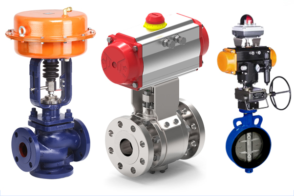
A valve is manufactured by assembling multiple mechanical parts, the key ones being the body (the outer shell), the trim (the combination of the replaceable wetted parts), the stem, the bonnet, and an actioning mechanism (manual lever, gear, or actuator).
Valves with small bore sizes (generally 2 inches) or that require high resistance to pressure and temperature are manufactured with forged steel bodies; commercial valves above 2 inches in diameter feature cast body materials.
The valve market is rather huge in terms of revenues and number of dedicated workers: it was worth approximately 40 billion USD per year in 2018. The major manufacturers of oil & gas valves are located in the US, Europe (Italy, Germany, France, and Spain), Japan, South Korea, and China.
In conclusion, valves are fundamental to the safe, efficient, and effective operation of the oil and gas industry, ensuring that energy resources are extracted, processed, transported, and stored with precision and care. Their variety and adaptability make them indispensable tools in the complex systems that fuel the modern world.
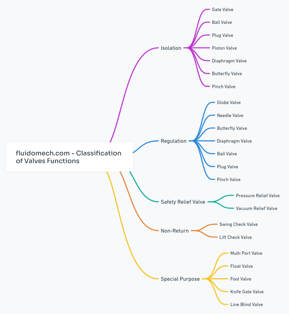
VALVE TYPES
Valves used in the oil and gas industry and for piping applications can be classified in multiple ways:
BY DISC TYPE (LINEAR, ROTARY, QUARTER TURN)
In the diverse world of valves, categorizing them by their operational mechanics—specifically, how they move to regulate flow via the disc —provides insight into their suitability for different applications in industries like oil and gas, water treatment, and chemical processing.
Let’s explore the distinctions between linear motion valves, rotary motion valves, and quarter-turn valves to understand their functionalities, advantages, and typical uses.
Linear Motion Valves
Linear motion valves operate by moving a closure element in a straight line to control the flow of fluid. This category includes:
- Gate Valves: Utilize a flat gate that moves vertically to the flow, providing a straight-through pathway when open and a secure seal when closed.
- Globe Valves: Feature a plug that moves up and down against the flow, offering precise flow regulation and the capability to stop flow entirely.
- Diaphragm Valves: Employ a flexible diaphragm that moves up and down to permit or restrict flow.
Advantages:
- Precise control of flow and pressure.
- Suitable for on/off and throttling applications, particularly where flow rate control is essential.
Typical Uses:
Situations requiring tight shut-offs and flow regulation, such as in water treatment plants and in the control of gas or steam.
Rotary Motion Valves
Rotary motion valves rotate a disc or ellipse about an axis to control fluid flow. This group encompasses:
- Ball Valves: Contain a ball with a hole through it, which rotates 90 degrees to open or close the flow path.
- Butterfly Valves: Have a disc mounted on a rod, which rotates to allow or block flow.
Advantages:
- Compact and lightweight design.
- Quick operation with low torque requirements.
- Generally lower in cost than linear motion valves for the same size and rating.
Typical Uses:
Broadly used in applications requiring rapid operation and space-saving solutions, such as in the chemical industry and for water distribution systems.
Quarter-Turn Valves
Quarter-turn valves are a subset of rotary motion valves that operate with a simple 90-degree turn of the handle or actuator to go from fully open to fully closed positions, or vice versa. This category includes Ball Valves and Butterfly Valves, as mentioned above, due to their quarter-turn operation.
Advantages:
- Speed and ease of operation.
- Effective shut-off capabilities, making them ideal for both isolating and control applications.
- Versatility in handling a wide range of media, pressures, and temperatures.
Typical Uses:
Extensively used across various sectors, including oil and gas for pipeline flow control, in manufacturing processes, and in HVAC systems for controlling water flow and temperature.
In summary, the choice between linear motion, rotary motion, and quarter-turn valves depends on specific application requirements such as the need for precise flow control, space constraints, and operational efficiency. Linear motion valves excel in providing precise control and tight shut-off, rotary motion valves offer compact and quick solutions, and quarter-turn valves bring the best of rotary action in terms of speed and simplicity, making them versatile for a wide array of applications.
| Oil & Gas Valve Types |
Linear motion valves |
Rotary motion valves |
Quarter turn valves |
| Gate valve |
X |
|
|
| Globe valve |
X |
|
|
| Check valve |
|
X |
|
| Lift check valve |
X |
|
|
| Tilting-disc check valve |
|
X |
|
| Stop check valve |
X |
X |
|
| Ball valve |
|
X |
X |
| Pinch valve |
X |
|
|
| Butterfly valve |
|
X |
X |
| Plug valve |
|
X |
X |
| Diaphragm valve |
X |
|
|
| Safety Valve / Pressure Relief Valve |
X |
|
|
VALVES BY BODY MATERIAL (CAST, FORGED)
The distinction between cast and forged valves lies in their manufacturing processes, which fundamentally affect their physical characteristics, performance, and applications.
As a general rule, cast bodies are used for valves above 2 inches in bore size, whereas forged bodies are used for valves below 2 inches (or preferred to cast valves, regardless of the pipeline bore size, in mission-critical applications).
Both types of valves play critical roles in controlling the flow of liquids and gases in various industries, including oil and gas, power generation, and water treatment.
Understanding the differences between cast and forged valves is essential for selecting the right valve for a specific application, ensuring optimal performance, durability, and safety.
Cast Valves
Manufacturing Process
Cast valves are made by pouring molten metal into pre-shaped molds where it solidifies into the desired valve shape. The casting process can be done through various methods, including sand casting, investment casting, and die casting, each with its own set of characteristics regarding surface finish, dimensional accuracy, and intricacies of design.
Characteristics
- Versatility in Design: Casting allows for complex shapes and sizes, making it possible to produce valves with intricate internal geometries that would be difficult or impossible to achieve through forging.
- Material Variety: A wide range of materials can be cast, including various types of steel, iron, and non-ferrous alloys, offering flexibility in material selection based on the application requirements.
- Cost-Effectiveness for Complex Shapes: For complex shapes and larger sizes, casting can be more cost-effective than forging, especially for low to medium-volume production.
Limitations
- Potential for Defects: The casting process can introduce internal defects such as porosity, shrinkage cavities, and inclusions, which can affect the mechanical properties and integrity of the valve.
- Variability in Quality: Cast valves can exhibit variability in quality and material properties across different batches due to the nature of the casting process.
Forged Valves
Manufacturing Process:
Forged valves are created through the process of forging, where a piece of metal is heated and then deformed and shaped into the desired form using high pressure. Forging can be performed using various techniques, including open-die forging, closed-die forging, and ring rolling, depending on the desired final shape and characteristics.
Characteristics
- Strength and Durability: Forging produces valves with superior strength, ductility, and resistance to impact and fatigue compared to casting. The forging process aligns the grain structure of the metal with the shape of the valve, enhancing its mechanical properties.
- Consistency in Quality: Forged valves generally offer more uniformity and consistency in material properties, with fewer internal defects than cast valves.
- High Performance in Critical Applications: Due to their strength and reliability, forged valves are preferred in high-pressure, high-temperature, and other critical applications where safety and performance are paramount.
Limitations
- Design Limitations: Forging cannot achieve the same level of complexity and intricate internal features that casting can, especially for large or very complex valve designs.
- Cost Considerations: For high-volume production of simple shapes, forging can be cost-effective. However, for complex shapes or lower volumes, the cost may be higher than casting, particularly for large-sized valves.
In summary, the choice between cast and forged valves depends on the specific requirements of the application, including mechanical strength, pressure and temperature conditions, desired material properties, design complexity, and cost considerations. Forged valves are typically favored in high-stress, high-performance applications due to their superior strength and reliability, while cast valves offer greater design flexibility and cost-effectiveness for complex shapes and large sizes.
To learn more about the difference between steel casting and forging please refer to the linked article.
VALVES BY TYPE OF ACTUATION (MANUAL, ACTUATED)
Valves can also be categorized based on their method of operation into manually operated valves and actuated valves. Understanding the differences between these two types is crucial for selecting the appropriate valve for a specific application, considering factors like ease of operation, control precision, and the necessity for automation.
Manually Operated Valves
Characteristics
- Operation: Manually operated valves require physical effort by an operator to change their position, using handwheels, levers, or gears. The manual input directly controls the opening, closing, or throttling of the valve.
- Design Simplicity: These valves are simpler in design as they do not require additional equipment for operation, making them straightforward to install and maintain.
- Cost-effectiveness: Without the need for external power sources or automation equipment, manually operated valves are generally more cost-effective than their actuated counterparts.
- Reliability: With fewer components that could fail, manually operated valves are highly reliable and suitable for applications where valve adjustments are infrequent or where direct manual control is preferred.
Limitations
- Labor Intensive: For systems requiring frequent adjustments or in situations where valves are not easily accessible, manual operation can be labor-intensive and time-consuming.
- Lack of Remote Control: Manual valves cannot be operated remotely, limiting their use in large, complex systems or in hazardous environments where remote operation is necessary for safety.
Actuated Valves
Characteristics
- Operation: Actuated valves are equipped with an actuator that allows valve operation (open, close, or modulate) through electrical, pneumatic, or hydraulic power. Actuators can be controlled remotely, allowing for automation and integration into control systems.
- Automation and Precision: With the ability to be controlled by various signals (electric, pneumatic, or hydraulic), actuated valves offer precise control over flow and pressure, enabling more efficient operation of the system.
- Flexibility and Safety: Remote operation capabilities allow actuated valves to be used in inaccessible, hazardous, or harsh environments, improving safety and operational flexibility.
- Adaptability: They can be integrated into automated control loops, responding to sensor inputs to adjust flow conditions automatically, which is essential for optimizing processes and ensuring safety in dynamic conditions.
Limitations
- Complexity and Cost: Actuated valves require additional components (actuators, power sources, control systems) making them more complex and expensive to install and maintain compared to manually operated valves.
- Power Requirement: Dependence on an external power source (electrical, pneumatic, or hydraulic) for operation can be a limitation in environments where such resources are limited or unavailable.
In summary, the choice between manually operated and actuated valves depends on several factors, including the need for automation, the operational environment, safety considerations, and cost. Manually operated valves are suitable for simpler, cost-sensitive applications where direct control and infrequent adjustments are sufficient. In contrast, actuated valves are ideal for complex systems requiring precise, remote, or automated control to enhance efficiency, safety, and operational flexibility.
VALVE BY DESIGN
Regarding their design, valves can be categorized in the following manner (it’s worth noting that our site features detailed articles on each type, so the descriptions provided here are intended to be broadly overviewed):
GATE VALVE
Gate valves are the most used type in piping and pipeline applications. Gate valves are linear motion devices used to open and close the flow of the fluid (shutoff valve). Gate valves cannot be used for throttling applications, i.e. to regulate the flow of the fluid (globe or ball valves should be used in this case). A gate valve is, therefore, either fully opened or closed (by manual wheels, gears, or electric, pneumatic and hydraulic actuators)
GLOBE VALVE
Globe valves are used to throttle (regulate) the fluid flow. Globe valves can also shut off the flow, but for this function, gate valves are preferred. A globe valve creates a pressure drop in the pipeline, as the fluid has to pass through a non-linear passageway.
CHECK VALVE
Check valves are used to avoid backflow in the piping system or the pipeline that could damage downstream apparatus such as pumps, compressors, etc. When the fluid has enough pressure, it opens the valve; when it comes back (reverse flow) at a design pressure, it closes the valve – preventing unwanted flows.
BALL VALVE
A Ball valve is a quarter-turn valve used for shut-off application. The valve opens and closes the flow of the fluid via a built-in ball, that rotates inside the valve body. Ball valves are industry standard for on-off applications and are lighter and more compact than gate valves, which serve similar purposes. The two main designs are floating and trunnion (side or top entry)
BUTTERFLY VALVE
Butterfly valves are versatile, cost-effective, valves to modulate or open/close the flow of the fluid. Butterfly valves are available in concentric or eccentric designs (double/triple), have a compact shape, and are becoming more and more competitive vs. ball valves, due to their simpler construction and cost.
PINCH VALVE
This is a type of linear motion valve that can be used for throttling and shut-off applications in piping applications that handle solid materials, slurries, and dense fluids. A pinch valve features a pinch tube to regulate the flow.
PLUG VALVE
Plug valves are classified as quarter-turn valves for shut-off applications. The first plug valves were introduced by the Romans to control water pipelines.
SAFETY VALVE
A safety valve is used to protect a piping arrangement from dangerous overpressures that may threaten human life or other assets. Essentially, a safety valve releases the pressure as a set value is exceeded.
CONTROL VALVE
Control valves are automated devices that are used to control and regulate the flow in complex systems and plants. More details about this type of valves are given below.
Y-STRAINERS
while not properly a valve, Y-strainers have the important function of filtering debris and protecting downstream equipment that may be otherwise damaged
VALVE SIZES (ASME B16.10)
To make sure that valves of different manufacturers are interchangeable, the face-to-face dimensions (i.e. the distance in mm or inches between the inlet and the outlet of the valve) of the key types of valves have been standardized by the ASME B16.10 specification.
ASME B16.34: VALVE COMPLIANCE
The ASME B16.34 standard, issued by the American Society of Mechanical Engineers (ASME), is a pivotal guideline that specifies the requirements for the design, material selection, manufacturing, inspection, testing, and marking of flanged, threaded, and welding end steel valves for application in pressure systems.
ASME B16.34 is also mentioned in the more general ASME spec ASME B31.1, “Power Piping Design”.
This standard is critical for ensuring the safety, reliability, and efficiency of valves used in various industrial sectors, including oil and gas, chemical, power generation, and water treatment, among others.
Understanding the ASME B16.34 standard is essential for engineers, manufacturers, and end-users involved in the selection and application of valves.
Key Aspects of ASME B16.34
- Valve Design and Construction:
ASME B16.34 sets forth the criteria for the design of valves, including dimensions, pressure-temperature ratings, and other factors essential for ensuring that valves can operate safely under specified conditions. It covers a range of valve types, such as gate, globe, check, ball, and butterfly valves.
- Pressure-Temperature Ratings:
One of the most critical aspects covered by ASME B16.34 is the pressure-temperature rating of valves, which defines the maximum allowable working pressure for a valve at a given temperature. These ratings ensure that valves are selected and used within their safe operating limits.
- Material Specifications:
The standard provides detailed specifications for the materials used in valve construction, including requirements for body, bonnet, trim, and gasket materials. These specifications ensure compatibility with the fluid being handled and the operating environment, contributing to the valve’s integrity and longevity.
- Testing and Inspection:
ASME B16.34 outlines the requirements for testing and inspecting valves to verify their integrity and performance. This includes tests for shell strength, seat tightness, and backseat effectiveness, among others, which are crucial for ensuring that valves meet stringent safety and reliability standards.
- Marking and Documentation:
The standard specifies the marking requirements for valves, which include the manufacturer’s identification, pressure-temperature rating, material designation, and other relevant information. These markings provide essential information for the identification, traceability, and selection of valves.
Importance of ASME B16.34 in Valve Selection
Adherence to the ASME B16.34 standard is crucial for ensuring that valves perform safely and effectively in their intended applications. Engineers and procurement specialists rely on this standard to select valves that meet the necessary performance criteria, including compatibility with the process medium, operating pressures and temperatures, and durability requirements.
Compliance with ASME B16.34 is also often a regulatory requirement in many industries, making it a key consideration in the procurement and installation of valves in critical applications.
Valve Compliance to ASME B16.34
A valve complies with ASME B16.34 when the following conditions are met:
- The valve body & shell materials comply with ASME and ASTM material standards for chemistry and strength
- Body & shell materials are heat-treated to ensure proper grain structure, corrosion resistance, and hardness.
- Wall thicknesses of the body and other pressure-containing components meet ASME B16.34 specified minimum values for each pressure class.
- NPT and SW end connections comply with ASME B1.20.1 or ASME B16.11.
- Stems are internally loaded and blowout-proof.
- All bolting will be ASTM grade with maximum applied stress controlled by B16.34.
- Each valve is shell tested at 1,5x rated pressure for a specific test time duration.
- Each valve is tested for seat leakage in both directions for a specific test time duration.
- Each valve is permanently tagged with materials of construction, operating limits, and the name of the manufacturer.
In conclusion, ASME B16.34 plays a fundamental role in the design, selection, and application of valves in pressure systems. It provides a comprehensive framework for ensuring that valves are safe, reliable, and suitable for their intended use, supporting the operational integrity of industrial processes across various sectors.
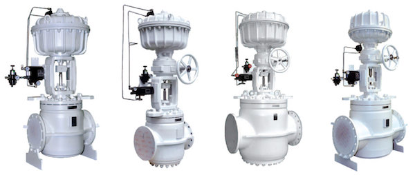
CONTROL VALVES
KEY CONCEPTS
Control valves are mission-critical devices in multiple process plants, ranging from oil & gas to industrial and nuclear applications. Control valves are used in irrigation systems, water treatment plants, oil and gas plants, power generation, fire prevention systems, pharmaceutical, and food processing industries by streamlining the response to changes in processes and providing greater safety to personnel and equipment.
The use of flow control valves has been increasing in the last years, due to growing process automation in most industries.
A control valve is a vital component used in various industrial processes to regulate the flow of fluids, such as gases, liquids, or slurries, by varying the size of the flow passage as directed by a signal from a controller.
This adjustment allows the control of process quantities such as pressure, temperature, and fluid level. In essence, control valves are the executive organs of control loops, playing a crucial role in automating process control to achieve desired specifications and enhance efficiency and safety in operations.
The operation of a control valve involves the manipulation of flowing media to match the demand of the process, which could involve either increasing or decreasing the flow rate. This is achieved by altering the position of a valve closure element — a disc, a plug, or a ball, among others — in response to signals from a control system. The control system, in turn, operates based on inputs from sensors that monitor the process conditions, ensuring that the valve’s operation is continuously adjusted to meet the desired outcomes.
A control valve is used in the oil and gas industry to regulate the flow rate of the fluid in a pipeline or process (and the related process parameters such as pressure, temperature, and level) according to signals managed by a controller. The role of a flow control valve in the complex petrochemical process is key, as the multiple loops involved in the process should be kept under strict and dynamic control to make sure that the process, as a whole, works as intended and produces the desired output in terms of quantity, quality and time.
TYPES OF CONTROL VALVES
Control valves come in various designs and types, each suited to specific functions and applications. The most common types include globe valves, ball valves, butterfly valves, and diaphragm valves. Globe valves, for instance, are known for their ability to provide precise flow control, making them ideal for applications that require accurate modulation of flow. Ball and butterfly valves, on the other hand, are appreciated for their quick operation and are often used in systems where rapid shut-off is necessary. Diaphragm valves excel in applications involving corrosive fluids or where hygiene is a priority, as their design minimizes crevices that could harbor contaminants.
SELECTION OF CONTROL VALVES
The selection of a control valve for a particular application is a complex process that considers several factors. These include the nature of the fluid to be controlled, the range of flow rates, the pressure differential across the valve, and the temperature of the process. Additionally, the valve material must be compatible with the process fluid to prevent corrosion or degradation. The control valve must also be sized accurately to operate efficiently across its expected range of conditions. Improper sizing can lead to issues such as valve wear, noise, and cavitation, potentially leading to system inefficiencies or failures.
Actuators are an integral part of control valves, providing the force required to operate the valve based on the control signal. Actuators can be pneumatic, hydraulic, or electric, with each type offering distinct advantages. Pneumatic actuators are popular in many industrial settings due to their reliability and simplicity. Hydraulic actuators provide high force in compact designs, suitable for high-pressure applications. Electric actuators offer precise control and are ideal for situations where pneumatic or hydraulic power is not available or practical.
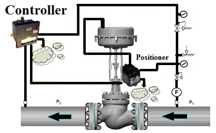
The opening and closing of the valve and its regulation are done by the combined effect of an electronic controller, a positioner, and the actuator of the valve. The actuator opens and closes the control valve in response to changes in key process parameters, such as changes in pressure, level, temperature, and flow. By such action, the process parameters are maintained within the required target range to make sure the process, as a whole, works as intended and produces an end product in the desired quantity and quality.
In summary, control valves are essential for the automated regulation of fluid flow in industrial processes, enabling the precise control of critical process parameters. Their selection and operation are fundamental to the safety, efficiency, and effectiveness of industrial systems. With advancements in materials, design, and control technology, control valves continue to evolve, offering improved performance and reliability to meet the demands of modern industrial applications. Their role in process control underscores the importance of precision engineering in the optimization of industrial operations, highlighting the interconnectedness of technology and industry in achieving operational excellence.
CONTROL VALVES TYPES
Control valves come in various designs, each suited to specific applications based on their operational mechanics and flow control capabilities. The main types of control valves can be broadly categorized into reciprocating (or linear motion) valves and rotary stem valves, each with distinct features and applications.
Reciprocating (Linear Motion) Valves
Reciprocating valves feature a stem that moves in a straight line to control the flow. This category includes several types of valves:
- Globe Valves: Known for their spherical body shape, globe valves use a plug that moves up and down within the valve body to regulate flow. They are well-regarded for precise throttling and control capabilities, making them ideal for applications requiring accurate flow regulation.
- Gate Valves: Utilize a flat gate that slides up and down perpendicular to the flow path. While primarily used for on/off control rather than throttling, gate valves provide a minimal pressure drop in the fully open position.
- Diaphragm Valves: Feature a flexible diaphragm that moves up and down to open or close the flow path. Diaphragm valves are particularly useful in applications involving corrosive fluids, slurries, or where purity and contamination prevention are critical.
- Pinch Valves: Employ a pinching mechanism to control flow by compressing a flexible tube or sleeve within the valve body. They are simple and effective for handling slurries or fluids with suspended solids.
Rotary Stem Valves
Rotary valves operate by rotating a closure element within the valve body to control flow. This group encompasses:
- Ball Valves: Utilize a spherical ball with a hole (bore) through its center. Rotating the ball 90 degrees opens or closes the flow path. Ball valves offer durable tight sealing and are suitable for on/off and throttling applications, handling a wide range of fluids and gases.
- Butterfly Valves: Feature a disc that rotates around a central axis within the valve body to regulate flow. Butterfly valves are known for their compact design and quick operation, making them suitable for large-volume flow applications and where space is limited.
- Plug Valves: Contain a cylindrical or tapered plug with one or more passages through it. Rotating the plug aligns the passages with the inlet and outlet ports to control flow. Plug valves are used for on/off control, throttling, and diverting fluid flow in various applications.
Specialized Control Valves
In addition to the basic types, there are specialized control valves designed for specific functions:
- Angle Valves: Similar to globe valves but with a 90-degree turn in the body design. Angle valves are used where space constraints prevent the use of a straight valve or where the flow direction needs to be changed.
- Three-Way Valves: Can mix flow from two inlets or divert flow to two outlets, useful in applications requiring fluid mixing or diverging.
Each type of control valve offers unique advantages and is chosen based on factors such as the nature of the fluid, flow rate requirements, pressure drop, and specific application needs. Understanding the operational characteristics and applications of different types of control valves is crucial for selecting the right valve to ensure efficient and reliable process control.
FLOW CONTROL VALVE COMPONENTS
Understanding the specific components of a control valve is crucial for appreciating how it functions within a system to regulate flow. Control valves are sophisticated devices designed to modulate the flow of fluids in response to signals from a control system. The primary components that constitute a control valve assembly include the valve body, the actuator, the positioner, and often, a controller. Each of these components plays a vital role in the valve’s operation, ensuring precise control over process conditions such as flow rate, pressure, and temperature.
Valve Body
The valve body is the primary casing of the control valve that contains the internal parts or trim (e.g., plug, seat, stem) responsible for flow modulation. It is the main fluid pathway through which the process fluid flows. The design of the valve body determines the flow direction, pressure drop, and overall suitability for specific applications. Materials for the valve body are selected based on compatibility with the process fluid, pressure and temperature conditions, and corrosion resistance.
Actuator
The actuator is a mechanism that moves the valve’s modulating element, such as the plug, ball, or disk, to adjust the flow passage based on the control signal. Actuators can be pneumatic, hydraulic, or electric. Pneumatic actuators use air pressure to generate movement, hydraulic actuators use liquid pressure, and electric actuators use electrical energy. The choice of actuator type depends on factors such as available power sources, control precision requirements, and environmental considerations.
Positioner
The positioner is a device that works in conjunction with the actuator to improve control valve performance. It receives a control signal from the process control system and converts it into an output signal that adjusts the actuator, ensuring the valve moves to the desired position accurately. Positioners compensate for variables that can affect valve positioning, such as friction, pressure fluctuations, and unbalanced forces, thereby enhancing the responsiveness and accuracy of the control valve.
Controller
While not always considered a direct component of the control valve assembly, the controller plays a crucial role in determining the valve’s position based on process variables. It processes signals from sensors that measure conditions such as flow rate, pressure, or temperature, and sends a control signal to the positioner to adjust the valve accordingly to maintain the desired setpoint. Controllers can be standalone devices or part of a larger distributed control system (DCS) or programmable logic controller (PLC) system.
In conclusion, the coordinated operation of these components—the valve body, actuator, positioner, and controller—allows a control valve to modulate flow precisely according to the requirements of the processing system. This synergy ensures optimal performance, efficiency, and safety in industrial processes, highlighting the sophisticated nature of control valve technology.
TYPES OF CONTROL VALVE ACTUATORS
Control valves’s actuators can be categorized based on the type of power they use to create motion—pneumatic, hydraulic, electric, and electro-hydraulic. Each type has its unique characteristics, advantages, and applications, making it suitable for specific operational requirements.
Pneumatic Actuators
Pneumatic actuators utilize compressed air to generate the force required to move the valve stem and alter the valve position. They are among the most commonly used actuators in process industries due to their simplicity, reliability, and cost-effectiveness.
Advantages:
- Rapid response time.
- Simple and reliable operation.
- Inherently safe in explosive environments as they do not generate sparks.
Applications: Widely used in the oil and gas, petrochemical, and water treatment industries, especially where safety and speed of operation are critical.
Hydraulic Actuators
Hydraulic actuators operate by using pressurized fluid (oil) to move the valve. They can exert a greater force than pneumatic actuators, making them suitable for operating large valves or valves that require significant force to move.
Advantages:
- High force output for their size.
- Good for high-pressure applications.
- Precise control over valve positioning.
Applications: Ideal for heavy-duty applications such as in the power generation, marine, and offshore industries where large valve sizes and high pressure are common.
Electric Actuators
Electric actuators use electric motors to drive the valve to the desired position. They are versatile and can be used in a wide range of applications, offering precise control and easy integration with digital control systems.
Advantages:
- Precise positioning and easy control integration.
- No need for compressed air or hydraulic fluid, simplifying installation and maintenance.
- Can be used in environments where pneumatic or hydraulic power is not available.
Applications: Suitable for various sectors including water treatment, HVAC, and manufacturing processes, particularly where precise control and feedback are required.
Electro-Hydraulic Actuators
Electro-hydraulic actuators combine the principles of hydraulic and electric actuators. They use an electric motor to drive a hydraulic pump, which then moves the actuator. This type offers the high force of hydraulic actuators with the precision and easy control of electric actuators.
Advantages:
- High force and precise control.
- Suitable for remote operation.
- Versatile, combining the benefits of electric and hydraulic systems.
Applications: Used in applications that require precise control and high force, such as in large valve operations in the oil and gas and power generation industries.
In conclusion, the selection of a control valve actuator depends on several factors including the required force, speed of response, control precision, environmental considerations, and available power sources. Understanding the characteristics and advantages of each type of actuator ensures optimal performance and reliability in controlling fluid flow across various industrial processes.
FLOW CONTROL VALVE ACCESSORIES
Cost is a major factor in material selection.
Not just the cost of material in dollars per pound, but also the cost of fabrication and inspection contribute to the uninstalled cost of the valve. Installed cost includes not only the cost of installation but also the cost of any damage from improper installation and the costs of the inspection.
The latter consists of such things as analysis of material chemistry, radiographic and surface examination of castings and welds, and check to see that the installed valve is the correct one and that it is properly oriented.
The selection of the appropriate or optimal control valve type depends on the particular study of the pipe system and the conditions of its fluid, but the size of the control valve should be such that pressure drops through it and not the drop of the pressure of the pipe is the one that controls the flow.
All valves, including steam control valves, are designed to meet an allowable internal leakage standard (FCI / ANSI). The higher the number of leaks, the lower the permissible internal leakage rate.
A Class I valve will have the highest internal leakage rate and usually the lowest cost; While a Class VI valve will have the lowest allowable internal leakage rate. Steam valves must be specified to have a leak rate of not less than Class IV. A class IV steam control valve will maintain a long service life.
CONTROL VALVE SELECTION
Selecting the appropriate control valve for a specific application is a critical decision in the design and operation of process systems. The right control valve not only ensures efficient process control but also contributes to the safety, reliability, and longevity of the system. The selection process involves considering multiple factors, including the characteristics of the fluid being controlled, the function of the valve in the process, and the operating conditions. Below is a structured approach to selecting a control valve:
1. Define the Process Requirements
- Fluid Characteristics: Understand the type of fluid (liquid, gas, or steam) the valve will control, including its corrosiveness, viscosity, presence of solids, and whether it is hazardous.
- Flow Requirements: Determine the maximum and minimum flow rates, normal operating flow rate, and required rangeability or turndown ratio of the valve to ensure it can accurately control flow across the expected range of operating conditions.
- Pressure Drop: Calculate the allowable pressure drop across the valve when fully open and during normal operation. The selected valve should be able to operate efficiently within the designed pressure drop.
2. Determine the Valve Type
Based on the application’s requirements, decide whether a linear (e.g., globe, diaphragm) or rotary (e.g., ball, butterfly, plug) valve is more appropriate. Consider factors like:
- Control Precision: Globe valves offer precise control, making them suitable for applications requiring accurate flow modulation.
- On/Off Operation: Ball and butterfly valves are well-suited for applications where quick and efficient on/off operation is needed.
- Special Fluids: Diaphragm and pinch valves are excellent choices for handling corrosive or slurry fluids where avoiding internal cavities is critical.
3. Select the Valve Size
- Sizing Calculations: Perform sizing calculations based on the flow requirements and the fluid properties. Use the manufacturer’s sizing software or manual calculations to determine the appropriate valve size that meets the flow conditions without causing excessive pressure drop or noise.
- Oversizing and under-sizing: Avoid oversizing the valve, as it can lead to poor control and stability issues. Undersizing, on the other hand, may not meet the flow requirements.
4. Material Selection
- Compatibility: Choose materials compatible with the process fluid to prevent corrosion and ensure the valve’s longevity. Common materials include stainless steel for corrosive fluids, brass or bronze for water applications, and special alloys for high-temperature or hazardous fluids.
- Temperature and Pressure: Ensure the selected materials can withstand the maximum operating temperature and pressure of the process.
5. Choose the Actuator Type
- Actuation Method: Decide between pneumatic, electric, hydraulic, or manual actuators based on power availability, control needs, and operating environment. Pneumatic actuators are common in process industries for their reliability and simplicity, while electric actuators offer precise positioning and are suitable for remote operation.
- Actuator Sizing: Ensure the actuator has sufficient force or torque to operate the valve under all process conditions, including any differential pressure across the valve.
6. Ancillary Components and Accessories
- Positioners: Consider adding a positioner for enhanced control accuracy, especially in modulating applications.
- Limit Switches, Solenoids, and Transmitters: Include necessary accessories for feedback, safety, and integration with the control system.
7. Review and Compliance
- Standards and Regulations: Verify that the selected valve meets industry standards (e.g., ASME, ANSI, API) and regulatory requirements for safety and environmental compliance.
- Manufacturer’s Data: Review technical datasheets and consult with manufacturers or specialists to confirm the suitability of the chosen valve for the intended application.
Selecting a control valve is a complex process that requires a thorough understanding of the process conditions, fluid characteristics, and operational requirements. Collaborating with experienced engineers and consulting with valve manufacturers can aid in making informed decisions that optimize process performance and safety.
CONTROL VALVES INSTALLATION
- Always expand the discharge steam line piping to at least one pipe diameter. It is not uncommon to expand the discharge piping by at least two or three pipe diameters. It should be noted that the expansion of the pipe reduces the valve outlet velocities thus prolonging the valve life. The valve manufacturer will provide the appropriate pipe size after the control valve. Match the pipe size to the heat transfer inlet connection.
- The distance after the steam control valve should be at least ten pipe diameters before the inlet connection of any heat transfer. In pressure reduction applications at least 20 horizontal pipe diameters must be left before a change of flow direction.
- The control valve must always be installed in a horizontal vapor line, never vertically.
- It is more important to properly select the valve at low flow operating conditions than at its assumed high flow operating conditions.
- Bypass valves must be used in the control valve installation. The by-pass valve is used to allow the personnel of the industrial facility to operate the process without the control valve if valve failure or maintenance is reactive, preventive, and predictive.
- Installing pressure gauges before and after the steam control valve allows the line diagnostics in real-time. The importance of proper installation cannot be overstated. In many cases, the source of a troublesome startup can be traced to a control valve that is not properly installed. It is strongly recommended that personnel with an instrumentation background be used at least to supervise the installation and setup of control valves.
HOW TO ORDER A VALVE
Manufacturers of valves used in the oil and gas industry need to know the following information to supply the right device:
- Valve type
- Bore size in NPS or DN
- Valve pressure rating (class range from 150# to 4500#)
- Specification (example API 6D, API 600, API 602, etc)
- Body and trim materials (at least)
- Required end connection (flanged, threaded, butt weld, lug and others)
- Fluid in the pipeline (>oil, gas, water, steam, solids)
- Working temperature and pressure
- Quantity
- Delivery time
- Origin restrictions (Chinese and Indian origins allowed or not)
EXAMPLE HOW TO ORDER OIL & GAS GATE, GLOBE, CHECK VALVES
Each manufacturer has own valves ordering sheets that map the valve configuration parameters that user has to consider:
GS – F – 6″ / 150 – 316 – B
1 2 3 4 5
| 1. Valve type |
2. End type |
3. Size / Class |
4. Body Material |
5. Options |
C: Check Valve
CL: Lift Check Valve
CS: Check pressure Sealed Valve
CW: Swing Check Valve
G: Gate Valve
GG: Forged Gate Valve
GL: Light Type Gate Valve (API 603)
GS: Gate Pressure Sealed Valve
O: Globe Valve
OB: Globe Bellowed Sealed Valve
OS: Globe Pressure Sealed Valve
Y: Y-strainer
|
F: Flanged End
T: Threaded End
W: Butt Weld End
S: Socket Weld End
|
Size: NPS 1/2 – 80″ ANSI Standard:
150: 150 LB Class
300: 300 LB Class
600: 600 LB Class
1500: 1500 LB Class DIN Standard: PN16
PN25
PN40 JIS Standard: 10K: JIS 10K
20K: JIS 20K
|
GG: Forged Gate Valve
316: Casting S.S CF8M
304: Casting S.S CF8
F316: Forgings S.S F316
F304: Forgings S.S F304
WCB: Steel WCB
LCB: Steel LCB
HB: Hastelloy B
IN: Inconel
|
B: By-Pass
G: Gear Operator
D: Drains
|